
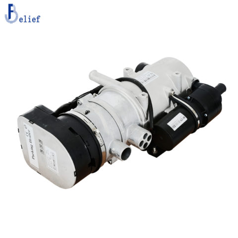
Liquid diesel heater 9KW 12V Belief


This liquid diesel heater is a smart engine coolant heater, it is with intelligent plateau function, APP remote control, Super quiet, Small size, Low fuel consumption, Large flow

 Liquid diesel heater 9KW 12V Belief
This Liquid diesel heater 9KW is a small fuel furnace controlled by a single-chip microprocessor. Its medium circulation system is connected with the cooling system of an automobile engine. In such a way, the cooling liquid for the engine can be heated by the heater while the engine is not working, so as to increase the temperature of the engine and the interior of the automobile.
With the help of the coolant parking heater, it is easy to start the engine even at very low temperatures and both the drivers and passengers can have a warmer environment.
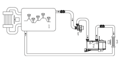
Working Principle
The cooling liquid of the engine flows through the water inlet pipe, the furnace cavity between the furnace inner casing and outer casing, and the water outlet pipe, forming a complete loop for the cooling liquid circulation system. The circulation is forced by the water pump. In this way, the cooling liquid of the engine can be heated again and again in the furnace, and the temperature of the engine, water-tank, heat-exchanger, and cab can rise gradually.
 Product advantages of Liquid diesel heater 9KW
- Super quiet
- Small size
- Low fuel consumption
- Large flow
- Bluetooth function
- Smart plateau function
- Stable performance
- Remote upgrade
- GSM control (Optional)
Application
 Important notes for users:
Be sure to read the instruction manual carefully before installation and use.
- Please check the vent on the fuel tank when doing installation
- Fuel pipe after clipping(must use blade, Scissors or pliers are forbidden) should ensure not affect fuel flow amount.
- Attention: The cooling liquid in use must be in conformity with the specifications of the automobile manufacturers. Anti-freezer not only can improve anti-freezing quality of the cooling liquid, but also can prevent corrosion. Therefore DO NOT add water in any case and only add cooling liquid in replacement.
-
If the temperature of cooling liquid is higher than 75°C, the heater can only be started after the temperature is reduced through pump circulation.
Power Supply
Heater power leads (positive and negative line) must be connected to the 12V/24V batteries directly. Battery more than 2 years which lack of electric frequently should be changed a new one in order to ensure normal use of the heater.
Fuel Supply
The fuel for the heater can be from the fuel tank in the car or from optional 5L independent fuel tank. The fuel pump is used for transmission of fuel and regulation of supply quantity of fuel.
Fuel pump installation
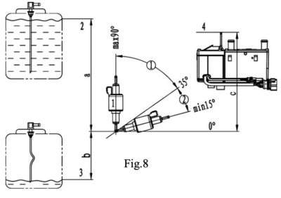 The optimum installation angle for the fuel pump is from 15 to 35 degrees, the allowable installation angle is from 35 to 90(max) degrees.
Attention for the fuel level, see attached photos.
Max.fuel level – 2
Min.fuel level – 3
Fuel inlet level – 4
Fuel standard
Gasoline should accord with standard DIN EN288
Diesel should accord with standard DIN EN590
Note: Fuel brand which used should meet the requirements of low temperature in winter. Biofuel is forbidden!
About APP control
Search in the app store for the MyBluee App and install via the app store.
Product Description of Liquid diesel heater 9KW
|
Heating medium |
Belief 9KW coolant parking heater |
|
Thermal power(W) |
9000 |
|
Power(W) |
2.6~10.5KW |
|
Fuel type |
Diesel |
|
Fuel consumption(l/h) |
0.3 ~ 1.1 |
|
Rated voltage |
DC12/24V |
|
Power consumption(W) (Without glow plug) |
36~66W/ 40~80W |
|
Working pressure (Mpa) |
0.2 |
|
Lowest working temperature |
-40℃ |
|
Working height above sea level |
≤5000m |
|
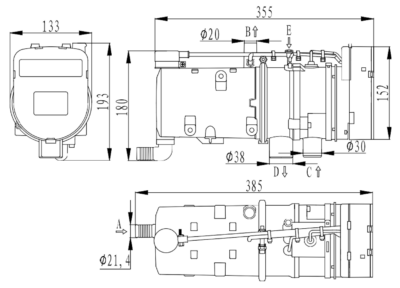
Weight of Main Heater (kg) |
4.7 |
|
GSM control(Optional) |
No limitation |
|
Coolant starting temperature |
45℃ |
|
CTN size (cm) |
51×34×33 |
|
Express(UPS/Fedex) Weight (kg) |
13 |
Features
- Intelligent plateau function
- Compact structure, small size, easy installation
- No need to start the engine, it can realize preheating in advance
- Avoid low temperature starting to bring wear to the engine
- High efficiency, fuel saving, emission reduction and environmental protection
- Mobile APP remote control
About us
Our factory was established in April 1998, located in Harbin, Heilongjiang province. We have an independent R&D organization and has established long-term cooperative relationships with state key universities and colleges like Harbin Institute of Technology, Harbin Engineering University, etc. Annual production is more than 150,000 sets. We exported to Europe, the United States, Canada, Japan, and etc 60 countries. We have sole dealers in AU and UK and Denmark.
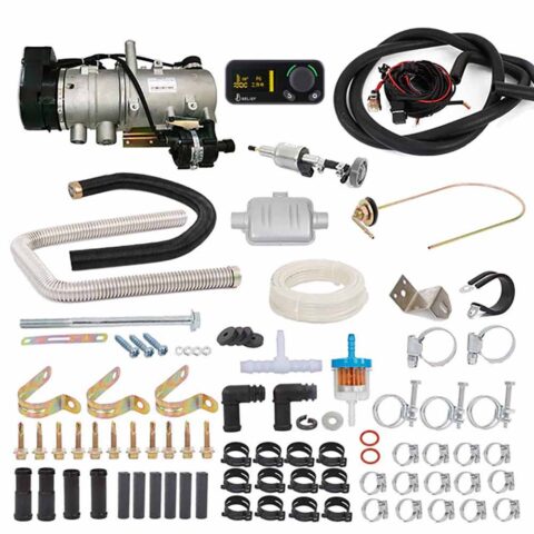
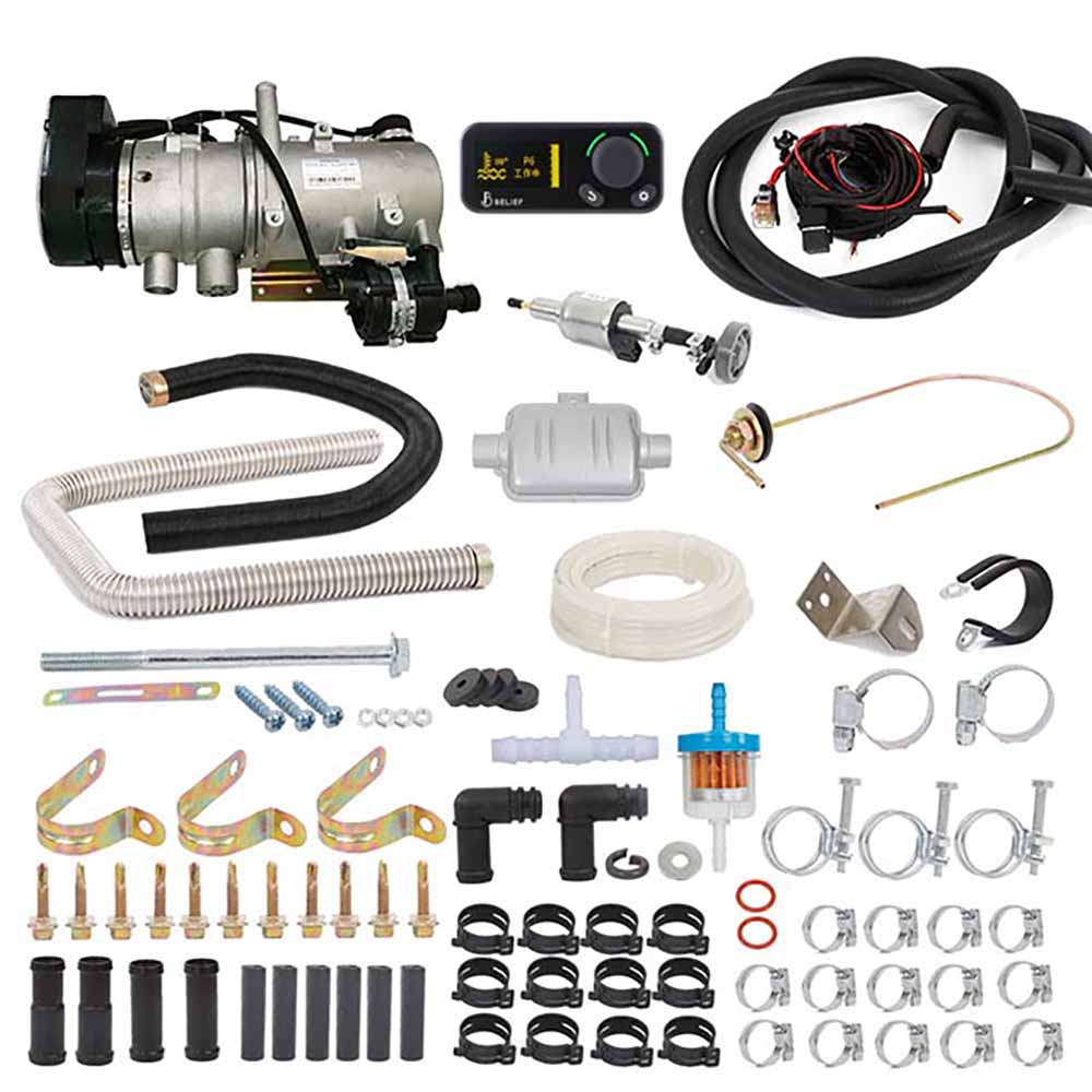
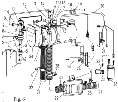
| No. | Name | Specifications | Amount |
| 1 | Parking heater | 5KW | 1 |
| 2 | Timer | 1 | |
| 3 | Fuel pump | YB-Ⅰ-12V(24V) | 1 |
| 4 | Muffler | XYQ-Ⅰ | 1 |
| 5 | Wiring harness | 1 | |
| 6 | Water pump | 12V (24V) | 1 |
| 7 | Heater bracket | 1 | |
| 8 | Rubber cushion | 4 | |
| 9 | Muffler bracket | 1 | |
| 10 | Air inlet pipe | Φ20.5/Φ24 L=900 | 1 |
| 11 | Exhaust pipe | Φ24/Φ29.5 L=1000 | 1 |
| 12 | Positive wire of power supply | 1 | |
| 13 | Fuse base | With cover | 1 |
| 14 | Fuse | QY169-5A | 1 |
| 15 | Fuse | 12V/20A(24V/15A) | 1 |
| 16 | Fuse | QY169-25A | 1 |
| 17 | Water pipe | Φ17/Φ27 L=2600 | 1 |
| 18 | Clip | 16-25 | 1 |
| 19 | Spring clip | Φ24×Φ27 | 10 |
| 20 | Oil pump clip | Φ32 | 1 |
| 21 | Oil pipe clip | 8-10 (9-11) | 12 |
| 22 | Exhaust pipe clip | Φ24-28 | 3 |
| 23 | Air inlet pipe fixing clip | Φ24 t=0.5 | 2 |
| 24 | Exhaust pipe fixing clip | Φ27 t=0.8 | 2 |
| 25 | Fuel pipe | GasolineΦ1.5×Φ4(DieselΦ2×Φ5) | 1 |
| 26 | Fuel pipe connector | Φ3.5/Φ9.5(Φ4.1/Φ10.5) | 6 |
| 27 | water pipe connector | Φ18 L=55 | 2 |
| 28 | Special water pipe connector | PPA +33 Φ20×Φ18 L=60 | 2 |
| 29 | Relay | 4141(only for 12V) | 1 |
| 30 | Filter | RYL-Ⅰ(only for diesel) | 1 |
| 31 | Bolt | M6×10 | 1 |
| 32 | Self drilling tapping screw | ST5.5×25 | 6 |
| 33 | Self drilling tapping screw | ST5.5×30 | 5 |
| 34 | Self tapping screw | ST3×20 | 1 |
| 35 | Self tapping screw | ST4×16 | 3 |
| 36 | Spring washer | Φ6 | 2 |
| 37 | Washer | Φ6/Φ12 | 2 |
| 38 | Nut | M6 | 1 |
| 39 | Fuel suction pipe | XYG-Ⅰ 3×400 | 1 |
| 40 | Plug | DJ7041A-2.8-21 | 1 |
| 41 | Nylon cable ties | 4×150 | 1 |
| 42 | Nylon cable ties | 4×200 | 1 |
| 43 | Instruction manual | 1 | |
| 44 | Reducing T | Φ6-Φ10/Φ10 | 1 |
| 45 | Oil pipe clip | 12-14 | 2 |
| 46 | Non-return valve | D18 | 1 |
| 47 | Transition elbow | 2 | |
| 48 | Fixing gear | 2 | |
| 49 | O-ring | 14.8×2.62 | 2 |
| 50 | Bolt | M6×95 | 4 |
Packing Heater Factory